Monitoring Well Installation: Design and Construction Standards
Technical guide to monitoring well installation for environmental assessment. Learn construction standards, sampling requirements, and regulatory compliance.
Monitoring Well Design Principles
Effective monitoring well design begins with understanding site hydrogeology and monitoring objectives. Screen interval selection is critical—the screened zone must intersect the target aquifer or contamination plume while avoiding cross-connection between aquifer units. Screen lengths typically range from 5-20 feet for water quality monitoring, with shorter intervals (2-5 feet) used for discrete zone sampling.
Filter pack sizing follows established gradation criteria to retain formation materials while allowing unrestricted groundwater flow. The filter pack (or gravel pack) grain size is typically selected based on formation sieve analysis, using a pack-to-formation ratio of 4:1 to 6:1 for the D50 particle size. Uniformity coefficients of 2.5 or less minimize segregation during placement.
Well diameter selection balances sampling requirements with installation costs. Two-inch wells accommodate most low-flow sampling equipment, while 4-inch wells allow for purge pumping and provide easier access for rehabilitation. Nested or multilevel well configurations allow monitoring multiple zones from a single borehole, reducing surface footprint while characterizing vertical contamination distribution.
Construction Methods and Materials
Hollow-stem auger drilling is the preferred method for unconsolidated formations, allowing sample collection during drilling and minimizing fluid introduction. Flight auger sizes of 6-1/4 to 10-1/4 inches accommodate standard 2-4 inch well casings with adequate annular space for filter pack and grout. Rotary drilling with mud or air is necessary for consolidated formations or depths exceeding auger capabilities.
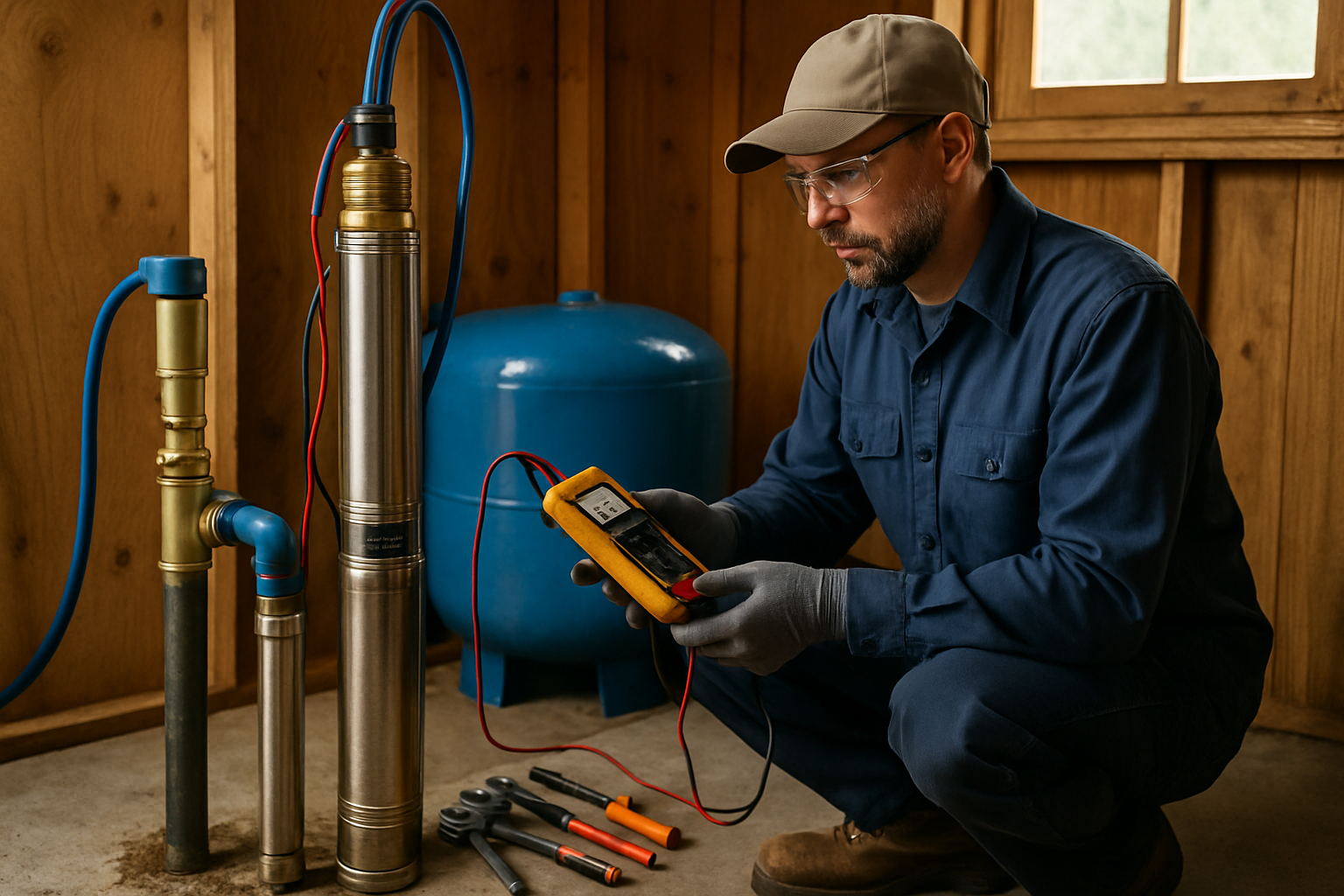
Casing materials must be chemically compatible with target analytes. Schedule 40 PVC is standard for most inorganic monitoring, while stainless steel (304 or 316) is required when monitoring for organics or where PVC may leach or sorb contaminants. Screen slot sizes of 0.010 to 0.020 inches are typical for fine-grained formations, with larger slots (0.020-0.040 inches) for coarser materials.
Annular seal requirements prevent surface water infiltration and cross-contamination between zones. Bentonite grout or cement-bentonite mixtures fill the annular space above the filter pack, extending to within 2 feet of surface. A concrete surface seal with protective casing completes the installation. All materials must meet NSF/ANSI 61 standards for drinking water contact.
Development and Sampling Considerations
Well development removes fine materials from the filter pack and formation, establishing hydraulic communication and ensuring representative sample collection. Common development methods include surging with bailers or surge blocks, overpumping, and mechanical agitation. Development continues until discharge water is clear and sand-free, with turbidity below 10 NTU and stable specific conductance readings.
Purge volume calculations determine the amount of stagnant water to remove before sampling. Traditional methods require purging 3-5 well volumes, but low-flow sampling techniques minimize purge requirements and reduce sample disturbance. Low-flow methods maintain drawdown below 0.3 feet while pumping at rates of 0.1-0.5 liters per minute, stabilizing indicator parameters before sample collection.
Dedicated sampling equipment eliminates cross-contamination between wells and reduces decontamination requirements. Bladder pumps and inertial pumps are preferred for volatile organic compound (VOC) sampling since they minimize sample agitation. Portable equipment requires thorough decontamination between wells using approved detergent solutions and deionized water rinses.
Regulatory Compliance and Documentation
EPA monitoring well guidance (RCRA, CERCLA) and state regulations establish minimum construction standards. California monitoring wells must comply with Department of Water Resources Bulletin 74-90 and regional water board requirements. Documentation includes well construction diagrams, boring logs, development records, and surveyed coordinates with elevations referenced to NAVD88 or other approved datums.
Well construction logs document all installation details including drilling methods, lithology, casing and screen specifications, filter pack intervals, seal materials, and surface completion. As-built diagrams show final well construction with depths, materials, and completion details. These records become part of the permanent site record and are required for regulatory submittals.
Chain of custody protocols ensure sample integrity from collection through laboratory analysis. Samples must be collected in laboratory-supplied containers, preserved appropriately, and maintained at required temperatures during transport. Holding times vary by analyte—some parameters require analysis within hours of collection. Proper documentation protects data quality and defensibility for regulatory and legal purposes.
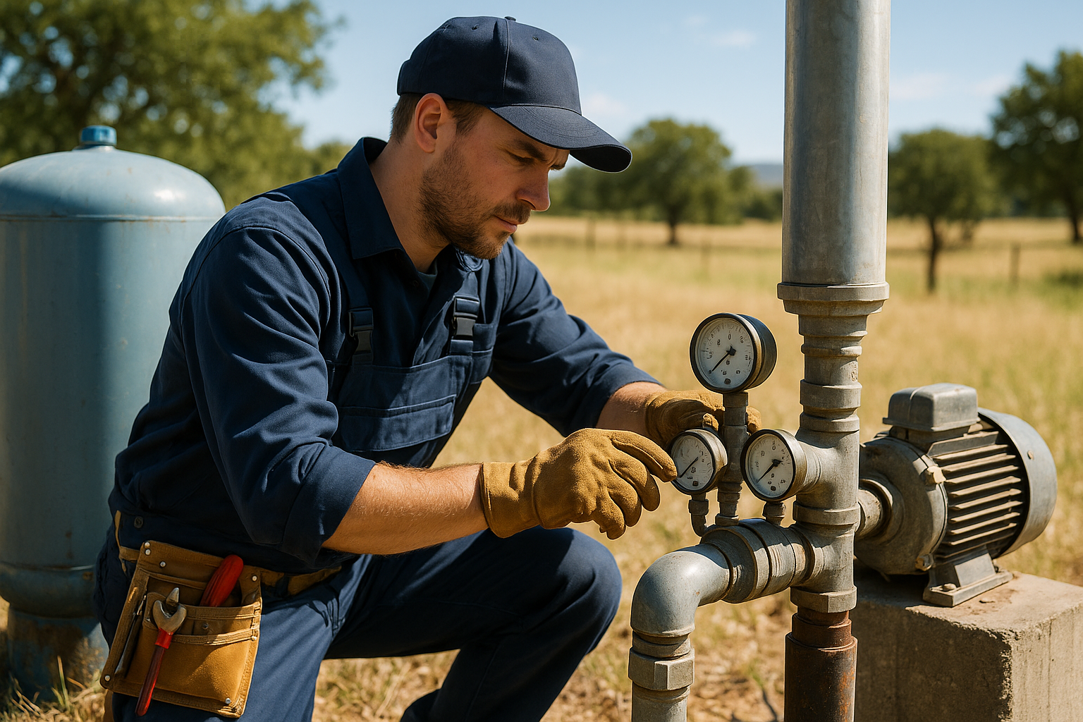
We service all major pump brands including Franklin Electric, Grundfos, Goulds (Xylem), and Sta-Rite (Pentair). Our trucks carry common parts and components for same-day repairs.
Frequently Asked Questions
What is the minimum diameter for a monitoring well?
The minimum diameter for most groundwater monitoring wells is 2 inches (Schedule 40 PVC), which allows for dedicated sampling equipment and water level measurements. However, 4-inch diameter wells are preferred for sites requiring purge pumping or larger sampling equipment. EPA guidance recommends 4-inch wells for RCRA compliance monitoring. Well diameter selection depends on sampling methods, aquifer yield, and regulatory requirements.
How long should you wait before sampling a new monitoring well?
New monitoring wells should undergo proper development before sampling, typically requiring 24-72 hours minimum after development for groundwater chemistry to stabilize. Many regulatory programs require waiting at least one week post-development before collecting baseline samples. For low-permeability formations, longer stabilization periods of 2-4 weeks may be necessary to ensure representative samples.
What is the difference between monitoring wells and piezometers?
Monitoring wells are designed for groundwater quality sampling, with longer screen intervals (5-20 feet) to collect representative water samples across the screened zone. Piezometers measure hydraulic head at a specific point, using short screen intervals (1-2 feet) or open standpipes. While both measure water levels, monitoring wells are built for sample collection with larger diameters and development requirements, whereas piezometers focus solely on pressure measurements.
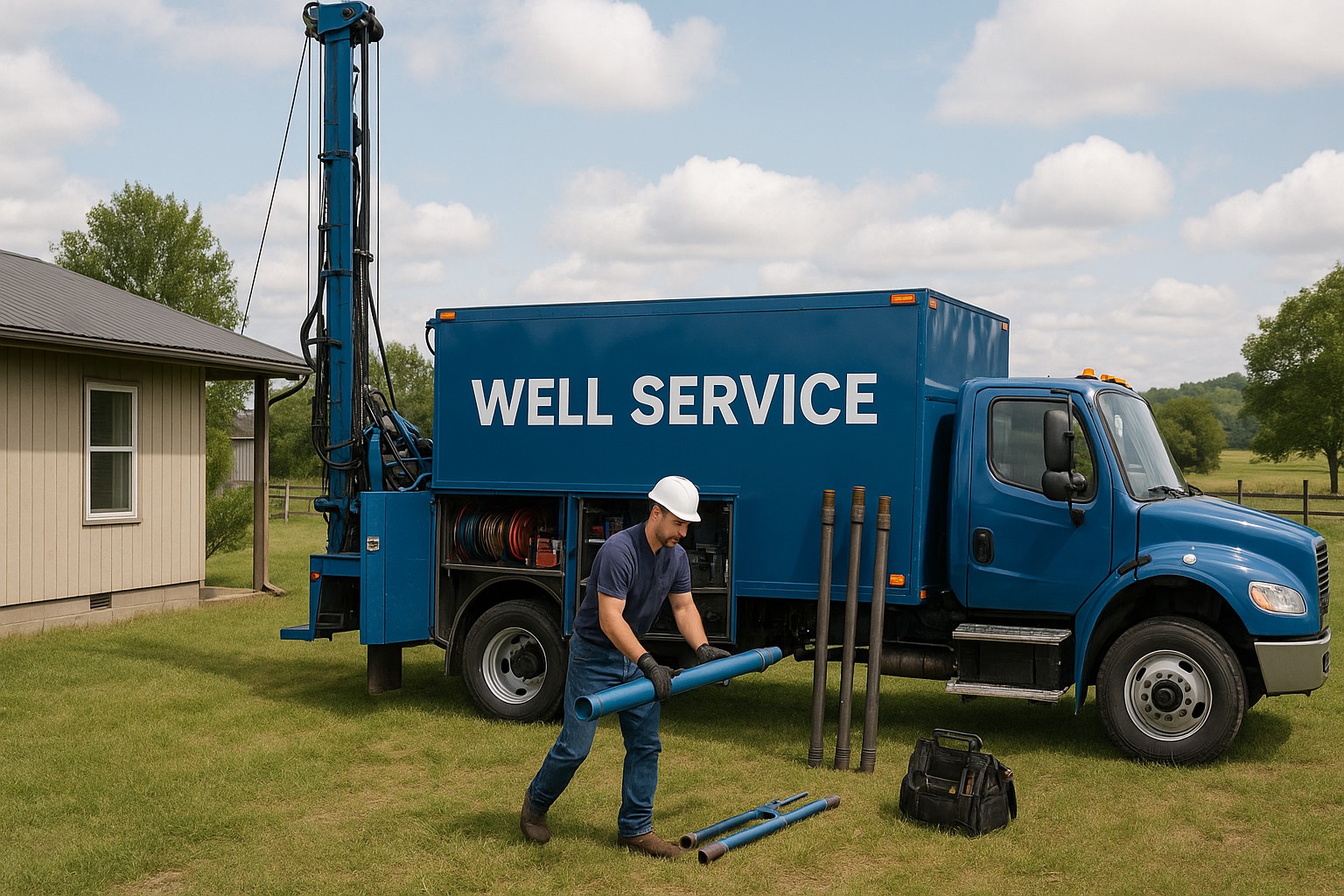
Get Expert Well Service
Southern California Well Service has served San Diego, Riverside, and San Bernardino counties for decades. Licensed C-57 contractor.
Call (760) 440-8520Available 24/7 for emergencies
Related Articles
Continue learning about well maintenance and troubleshooting